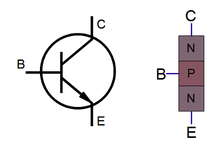
Get a transistor power rating meter to measure the hfe of your trannies and by using really low hfe transistors you might get closer to that Ge sound. Ge cleans up from the guitar better than Si in general which can be difficult to replicate, but a tone control or some kind of treble snubber in the circuit can help a silicon pedal sound more Ge. Germanium does have some sounds which are difficult to get from silicon but it's not impossible to get close enough. And no need for the reverse polarity chip either. Expanding on some of the other answers: Transistors have parasitic capacitance and FETs also have a gate capacitance. These features allow GaN transistors and integrated circuits to be used in circuits. In a PNP transistor, the type of the layers are reversed. By growing a GaN epi layer on top of silicon, the existing silicon. An NPN transistor has a piece of P-type silicon (the base) sandwiched between two pieces of N-type (the collector and emitter). Depending on what is added to the silicon, it will be either N-type or P-type. I still need to modify the circuit a bit to roll-off some of the treble but by using a 2N2222A with an hfe under 160 I have made some great sounding Red Rooster pedals. A bipolar junction transistor is made up of three pieces of silicon. My most successful use of Si instead of Ge has been in the Red Rooster (Chickenhead) treble booster. Of course with older transistors noise can become an issue, but if you replacing germanium perhaps not such an issue! How can I calculate R1, R2, RC and RE in the following silicon transistor circuit Ask Question.

Assume transistor is Silicon (a-0.98) IE Ic Rp 1.5 kQ Rc 1.2 kn VEE 8. Therefore the transistor is switched Fully-OFF. I've used some very old 2N3903s and 2N2222As. Solution for Problem5: For the common base circuit shown in figure find I. Cut-off Region Here the operating conditions of the transistor are zero input base current ( IB ), zero output collector current ( IC ) and maximum collector voltage ( VCE ) which results in a large depletion layer and no current flowing through the device. The transistor has three regions of different conductivity with two NPN junctions.

#TRANSISTOR SCHEMATIC SILICON DRIVERS#
It is used in a wide range of electronic equipment especially used as an audio signal amplifier and drivers using complimentary or quasi complimentary circuits. I have had good results in some circuits by subbing low-gain Si trannies for Ge. BD135 transistor is a bi-polar, medium-power, plastic nPn transistor made up of silicon. Well Ge transistors leak, and that can be a big part of why some fuzz circuits work with Ge but not so well with Si.


 0 kommentar(er)
